Champion Model 66 DRPW Specifiche
Navigare online o scaricare Specifiche per Barbecue & Griglie Champion Model 66 DRPW. Champion Model 66 DRPW Specifications Manuale Utente
- Pagina / 104
- Indice
- SEGNALIBRI
- Manual P/N 114725 rev. C 1
- ATTENTION: 2
- PRODUCT REGISTRATION 3
- Revision History 5
- LIMITED WARRANTY 6
- Table of Contents 7
- Model Descriptions 8
- Receiving 9
- ATTENTION 10
- (continued) 12
- 46-1/2" 15
- 31-1/2" 15
- B702285/0 17
- Utilities 18
- Drain Connections 19
- Ventilation Connections 19
- Electrical Connections 20
- L1 L2 L3 21
- Chemical Signal Connections 22
- Vent Fan Signal Connection 22
- Running Signal and 22
- Curtain Locations 23
- Door Safety Switches 24
- Scrap Screens 25
- Spray Arm Guide 26
- Components 27
- Installation 29
- Installing the Pawl Bar 30
- Installing the Curtains 31
- Check list 32
- Control Panel Operation 33
- Operation 34
- Cleaning 35
- Cleaning (continued) 36
- De-liming 36
- Maintenance 37
- Condition Cause Solution 38
- Service Replacement Parts 39
- Control Panel 40
- Control Cabinet 42
- Extended Vent Cowls 44
- (L-R Direction Shown) 46
- See Next Page 48
- L-R Direction Shown 52
- Fill Piping 54
- Final Rinse Piping 56
- MD-66 Prewash Spray Arms 58
- Rear of Hood 60
- MD-44 Track Assembly 62
- MD-66 Track Assembly 64
- Tank Bottom 72
- Pump/Motor Assembly 74
- Dish racks 86
- 1 101285 RACK, PEG 1 87
- Rack Control Module 89
- Electrical Schematics 89
- Rack Control 90
- Input Section 91
- NOT USED 91
- RCM Status/Jumpers 93
- Normal Operation Sequence 94
- Plate 1: 94
- Plate 2: 94
- Plate 3: 95
- Plate 4: 95
- Plate 6: 96
- Plate 5: 96
- Plate 7: 97
- Plate 8: 97
- Plate 9: 98
- Plate 10: 98
- !! IMPORTANT !! 99
- Plate 12: 100
- This Page 104
- Intentionally 104
- Left Blank 104
Sommario
Installation/Operation Manual with Service Replacement Parts 2674 N. Service Road, Jordan Station Ontario, Canada L0R 1S0905/562-4195 Fax: 905/562-
2MD-44 Direction Field ConversionATTENTIONConversion must be performed BEFORE the machine is permanently located and utilities connected. Access to t
92Front Panel Power Switch Turned Off while Dishwasher is In-cycleRack Control Module OperationPlate 12:1. Door closed.2. POWER Switch OFF.3. Float
93Circuit Board Jumper Settings MD44 = No jumpers installed MD66 = Prewash jumper installed DR Tank & Rinse Tank Jumpers not used
96This Page Intentionally Left Blank
3MD-44 Direction Field ConversionMD-44 Direction Field ConversionRefer to the illustration on the previous page and note that machine assemblies are n
4MD-44 Direction Field Conversion (continued)MD-44 Direction Field Conversion5. Removing the final rinse manifold requires that the rear track be unf
58. Remove the rinse drain piping from the unload end of the tank. To do this, remove three sections of black hose connecting the drain piping toge
6MD-44 Direction Field Conversion (continued)MD-44 Direction Field Conversion10. R-L to L-R Conversion ONLY Rotate the drain piping assembly removed i
7MD-44 Direction Field ConversionMD-44 Direction Field Conversion12. L-R to R-L Conversion ONLY Rotate the drain piping assembly removed in Step 8 180
813. Remove the junction box cover and identify the large terminal block located in the top left corner of the box. See the illustration below. 14. Re
9MD-44 Direction Field ConversionMD-44 Direction Field ConversionMOTORDRIVE PUMPWASH323331HI LIMITTSTATHARNESS FROM MAIN CABINETFINAL151413533333RINSE
10NOTE: Only qualified personnel should make dishwasher plumbing connections. Connections must meet local plumbing and sanitary codes. Improper instal
11InstallationDrain Connections1. The 1-1/2" drain line was removed and packed inside the dishwasher prior to shipping. Install the drain li
COPYRIGHT © 2013 All rights reserved Printed in the USAFor future reference, record your dishwasher information in the box below. Model Number__
12MACHINE ELECTRICAL CONNECTION!!ATTENTION!!Electrical and grounding connections must comply with the National Electrical Code or in the absence of a
131. Motor rotation was set at the factory. 2. The conveyor drive motor rotation is indicated by a red arrow located on the side of the motor.3.
141. Use a qualified detergent/chemical supplier for detergent/chemical and dispensing equipment needs.2. Labeled detergent control circuit connec
15InstallationCurtain Locations1. Refer to the illustrations below and hang the curtains as shown. J-hooks are located in the corners of each secti
16Dishwasher access doors are equipped with a door safety switch that automatically stops the dishwasher pumps and conveyor drive if a door is raised
17InstallationScrap Screens1. The model MD-44 and the MD-66 have scrap screens in the top of the wash tank. Install four scrap screens in the wash ta
18InstallationInstalling the Lower Spray arm AssemblySpray Arm O-ringLower Spray Arm Latch Spray Arm Guide1. The lower spray arm assembly isconnected
19Installing the Upper Spray Arm AssemblyInstallation1. Upper Wash Arm Rear Support The rear support holds the wash arm and serves as a guide whe
201. Upper Wash Arm Rear Guide Pin The rear guide pin is attached to the rear of the upper wash arm. It mates with the upper wash arm rear sup
21Installing the Upper Spray Arm AssemblyInstallation345Upper Wash ArmRear SupportUpper Wash Arm Front SupportsUpper Wash Arm AssemblyConnection Flang
PRODUCT REGISTRATION ONLINETHE ADDRESS BELOW TO REGISTER YOUR PRODUCT ONLINEMAKE SURE YOU ARE CONNECTED TO THE INTERNETTHEN ENTER http://www.champion
22InstallationInstalling the Pawl BarCrossheadBrass Crosshead RollerGuide RollerPawl Bar1. Position the pawl bar on the guide rollers located at each
23InstallationInstalling the CurtainsShort CurtainJ-hookLong CurtainMedium Curtain1. Curtain are equipped with curtain rods. The rods are hung on J-ho
241. Remove white protective film from the dishwasher exterior.2. Install lower panels to the dishwasher.3. Remove any foreign material from inside
25OperationControl Panel OperationThe final rinse pressure gauge is located behind the control panel. The top-mounted control panel contains the Powe
26Operation 1. Check that the spray pipes, curtains, and scrap screens are in place and clean.2. Check that the overflow drains are closed.3. Check
27CleaningCleaning your dishwasher is the best maintenance you can do. The cleaning intervals below are the minimum requirements for most dishwashers.
28CAUTION: De-liming agents can cause chemical burns. Wear rubber gloves, eye protection and any other protective clothing as instructed by a qualifi
29Weekly1. Inspect all water lines for leaks and tighten at joints if required.2. Clean any detergent residue from the exterior of the machine.3. C
30Condition Cause SolutionDishwasher will not run.Low or no water.Door not closed.Main power OFF.Dishwasher OFF.Dish rack inserted wrong Main water
31Service Replacement PartsIllustrations PageControl Panel ...
PRODUCT REGISTRATION BY FAX (336) 661-1660 in the USA1-(800) 204-0109 in CanadaIMPORTANT IMPORTANTModelSerial #Date of Installation:Company Name
Control Panel110111278823465519932
Control Panel1 100097 SCREW, TRUSS HD., 10-32 X 1/2" SST 32 333533 COVER, CONTROL CABINET 13 114768 DECAL 36" CONTROL CABINET 3-HOLE
Control Cabinet910567812341111 1112132214171920232425262721181516SIGNAL ONLYLIMITTABLERUNNINGMACHINESWITCH34
Control Cabinet1 113936 LABEL, TABLE LIMIT SWITCH/ MACHINE RUN 12 107171 TERMINAL BLOCK, 4-POLE 13 111153 FUSE BLOCK, 600V 30A 24 112482 FU
Extended Vent Cowls15782349636
Extended Vent Cowls1 100073 SCREW, 1/4-20 X 1/2" TRUSS HD., SST 62 106026 WASHER, 1/4" FLAT 63 106482 WASHER, LOCK 1/4" SPLIT
Wash Tank Door, Panels and Curtains (L-R Direction Shown)1 2 3 4 4 5 6 9 12 13 14 15 16192018192111 20241 222223257 8 10 1717181838
1 100212 SCREW, 10-32 X 3/4" TRUSS HD. 42 108250 ROD, CURTAIN 13 109723 CURTAIN, 24" X 6-1/4" (RINSE CURTAIN) 14 113691 GUID
Wash Tank Heat, Float Switch, and Scrap ScreensTo Booster1 3 4 4 6 9 10 11 13 20 22 1523 2421 2828272625 21 29 14 17 18 19 162 2 12 14 5 7 8 HH = High
Wash Tank Heat, Float Switch, and Scrap Screens1 100154 HEX PLAIN NUT, 5/16-18 SST 42 100547 LOCKNUT, 1/2" NPT SST 33 100740 BOLT, HEX HD
iRevision HistoryRevision HistoryA revision might be a part number change, new instructions, or information that was not available at print time. We
Wash Tank Junction Box Terminal Block4211352467
Wash Tank Junction Box Terminal Block1 114519 END BLOCK, E/NS 35N 22 114514 TERMINAL, SINGLE, ST 2.5 WH (WHITE) 13 114517 TERMINAL, DOUBLE STT
MD-66 Prewash Tank, Door and Curtains312923232825242627530141019121615181722192021221214138911173624L-R Direction Shown44
MD-66 Prewash Tank, Door and Curtains1 100547 LOCKNUT, 1/2" NPT SST 12 102376 WASHER, FLAT 5/16" 312 108250 ROD, CURTAIN 13 10488
Fill Piping(R-L Direction Shown)46To BoosterInletMain WaterConnection 1 12 20 2 3 3 3 3 4 5 5 3 6 7 7 8 9 10 11 13 14 15 16 17
Fill Piping1 100135 GAUGE, PRESSURE 0-60 PSI 12 100171 BUSHING, RED. FACE 3/4" X 1/2" BRASS 13 100184 NIPPLE, 3/4" NPT X CLOSE
Final Rinse Piping 3 5 4 4 5 2 1 6 7 48
Final Rinse Piping1 100156 LOCKNUT, 3/4" NPT, BRASS 12 108620 GASKET, RINSE MANIFOLD, 3/4" PIPING 13 111203 NOZZLE, VEE-JET #8003 4
MD-66 Prewash Spray Arms 1 2 4 3 5 7 8 8 12 6 9 10 11 13 Rear of Hood 14 50
MD-66 Prewash Spray Arms1 100154 HEX PLAIN NUT, 5/16-18 SST 42 100734 BOLT, HEX HEAD, 1/4-20 SST 43 102376 WASHER, FLAT 5/16" SST 44 10
iiLimited WarrantyLIMITED WARRANTYMoyer Diebel, 3765 Champion Boulevard, Winston-Salem, North Carolina 27105, and P.O. Box 301, 2674 N. Service Road
MD-44, MD-66 Wash Spray ArmsRear of Hood 2 4 20 19 14 18 172 10 12 16174671379 15 11 3 6 8 1 10 19 20 20 4 8 8 52
MD-44, MD-66 Wash Spray Arms1 100154 HEX PLAIN NUT, 5/16-18 SST 42 100734 BOLT, HEX HEAD, 1/4-20 X 1/2" SST 43 102376 WASHER, FLAT 5/16&q
MD-44 Track Assembly 2 5 6 7 12 13 1 7 15 16 3 4 7 8 9 11 10 14 11 8 (L-R Direction Shown)54
MD-44 Track Assembly1 100734 BOLT, HEX HD., 1/4-20 X 1/2" SST 82 100735 BOLT, HEX HD., 1/4-20 X 5/8" SST 83 100736 BOLT, HEX HD., 1/
MD-66 Track Assembly 1 3 5 5 7 6 4 7 6 7 5 2 8 9 1 7 13 10 14 18 17 16 15 12 11(L-R Direction Shown)56
MD-66 Track Assembly1 100734 BOLT, HEX HD., 1/4-20 X 1/2" SST 82 100735 BOLT, HEX HD., 1/4-20 X 5/8" SST 83 100736 BOLT, HEX HD., 1/
MD-44 Pawl Bar Assembly117224658399691112124910106615151619202114131718161658
MD-44 Pawl Bar Assembly1 100141 HEX GRIP NUT, 1/4-20 SST CTR LOCK 92 114824 SPACER, PAWL BAR 103 204513 PAWL, CRADLE 54 100002 BOLT, 1/4-20
MD-66 Pawl Bar Assembly1171522223410968654911121210616192014131718182021691616(L-R Direction Shown)60
MD-66 Pawl Bar Assembly1 100141 HEX GRIP NUT, 1/4-20 SST CTR LOCK 102 114824 SPACER, PAWL BAR 163 204513 PAWL, CRADLE 84 100002 BOLT, 1/4-2
iii MD-44 and MD-66 Rack Conveyor DishwashersRevisions to this manual...
115231645151776891071413121111137Drive Motor Assembly62
Drive Motor Assembly1 0509199 DRIVE MOTOR SWITCH 12 327918 BRACKET, MOTOR SWITCH MOUNTING 13 113893 SHEAVE, MOTOR AK51, 5/8" BORE 14 32
1415212224232524201919212017134576891011121318216Tank Bottom Conveyor Drive Assembly64
Conveyor Drive Assembly1 202381 ROLLER, CROSSHEAD 12 100868 STUD, CROSSHEAD ROLLER 13 107089 NUT, JAM 1/2-13 14 206300 CRANK, RACK ARM 15
Pump/Motor Assembly3 2 166
Pump/Motor Assembly67Item No. Part No. Description Qty. 1 114347 PUMP/MOTOR ASSEMBLY (INCLUDES ITEMS 2-3) 1 208-240/460/60/3 2HP2 108002
MD-44 Pump Installation10 11 13 12 18 8 1715334611614274459561Wash68
MD-44 Pump Installation1 100154 HEX PLAIN NUT, 5/16-18 SST 82 100739 BOLT, HEX HD., 5/16-18 X 3/4" SST 43 100740 BOLT, HEX HD., 5/16-18 X
MD-66 Pump Installation2619 20 8 13 10 45594618 12 3 3 4 4 6 1 PrewashWash10 11 13 12 18 8 153346116144459561211770
MD-66 Pump Installation71Item No. Part No. Description Qty. 1 100154 HEX PLAIN NUT, 5/16-18 SST 162 100739 BOLT, HEX HD., 5/16-18 X 3/4&quo
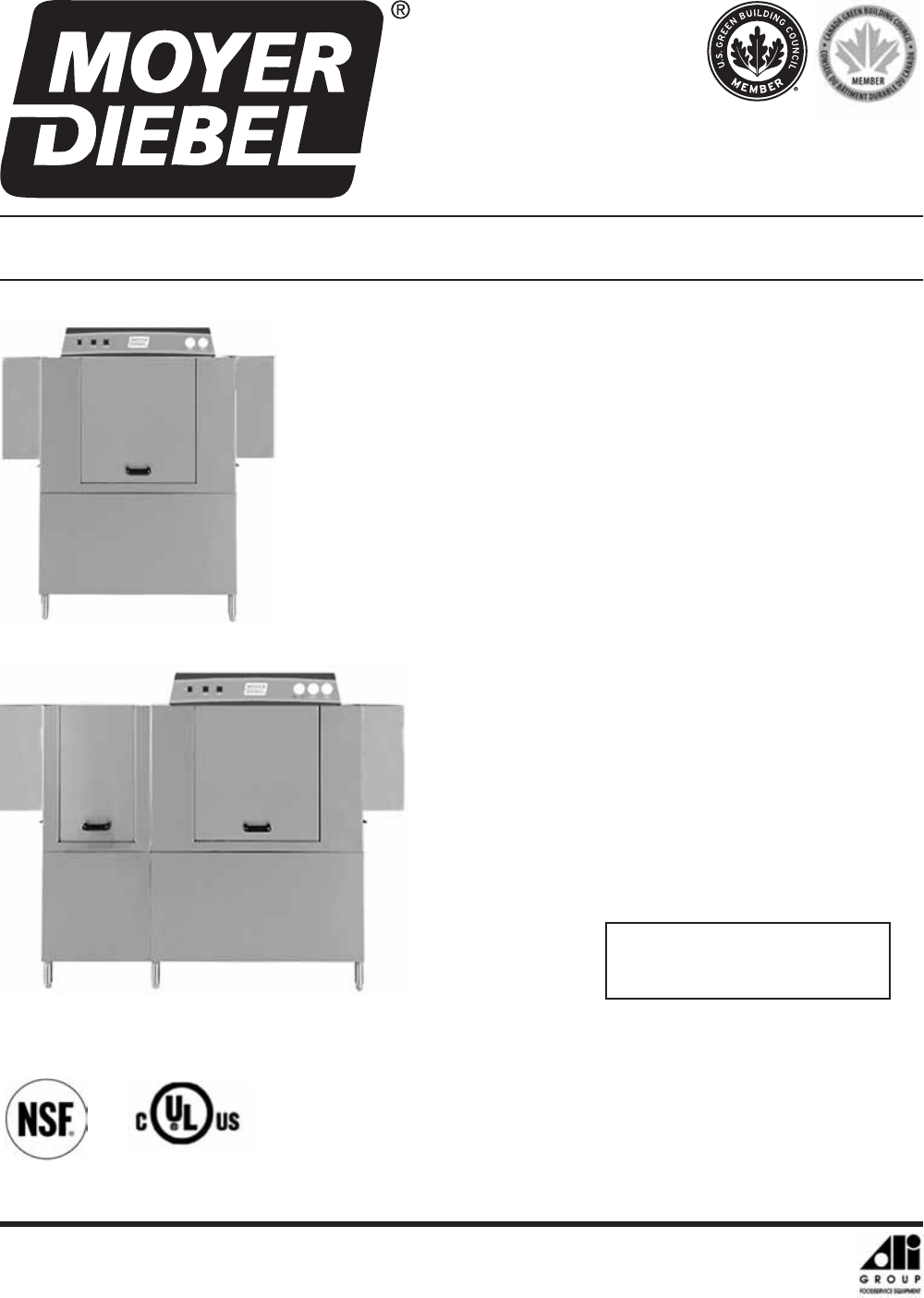
ivModel DescriptionsModel MD-44 Electric high temperature single tank rack conveyor dishwasher with a built-in electric booster in 40°F/22°C rise or
Electric Booster Assembly - 40°F and 70°F Rise1913161271718202122232422254141548569911104132WaterInletTo Final Rinse(L-R Direction Shown)72
Electric Booster Assembly - 40°F and 70°F Rise4 109985 SEAL, ELECTRIC HEATER FLANGE 35 100003 NUT, PLAIN 1/4-20 SST 96 106482 WASHER, LOCK 1/
MD-44 Drain Assembly Model3 2030312529172219161128299712131111248564102327110142621151824(L-R Direction Shown)74
MD-44 Drain Assembly1 100036 TEE, 1-1/2" NPT GALVANIZED 12 100043 NIPPLE, 1-1/2" NPT X CLOSE, GALVANIZED 13 100113 CAP, 3/4" NP
MD-66 Drain Asssembly5 13 6 8 9 11 13 14 15 15 16 17 18 20 20 25 26 27 28 30 33 34 1 3 1 2 4 7 10 12 19 21 22 23 24 21 2 32 32 23 31 36 31 1 13 37 29
MD-66 Drain Assembly1 100036 TEE, 1-1/2" NPT GALVANIZED 32 100043 NIPPLE, 1-1/2" NPT X CLOSE, GALVANIZED 33 100589 UNION, 1-1/2"
12Dish racks78
Dish racks1 101285 RACK, PEG 12 101273 RACK, COMBINATION 179Item No. Part No. Description Qty.
Blank PageThis Page Intentionally Left Blank80
Rack Control Module Operation and Electrical Schematics81
1Installation!!ATTENTION!!Use caution when moving or lifting the dishwasher to prevent damaging the dishwasher or the installation site. Check doorwa
82Rinse Flt LWash Flt LWash Flt UFinal RinseRack SwitchJam SwitchTable LimitStopStartPausePowerDR LevelRinse Flt UPrewash Flt LPrewash Flt URunH7H5 H3
83Rack Control Module (RCM) Operation(RCM)H3(MD-66 Only)(MD-66 Only)The operation of the dishwasher and the RCM is apparent by observing the status of
84H1H2H4H6DR PumpPumpsRinse AidPrewash FillWash FillFinal RinseRun LightDR/Rinse HeatWash HeatBooster HeatOutput SectionNOT USEDNOT USEDRack Control M
85Rack Control Module OperationThe timer controls the drive motor, wash pump and the MD-66 prewash pump. The timer is internal to the RCM. The PUMPS
86Rack Control Module (RCM) Indicator Lights Normal Operation SequenceRack Control Module OperationRinse Flt LWash Flt LWash Flt UFinal RinseRack Swit
87Plate 3:1. Doors closed.2. POWER light ON.3. Floats up.4. Tanks full.5. Tank heat enabled.6. Booster heat enabled.7. Initial fill complete.8.
88Rack Control Module OperationPlate 6:1. Doors closed.2. Power light ON.3. Floats up.4. Tanks full.5. Tank heat enabled.6. Booster heat enabled
89Rack Control Module OperationDoor Opened while Dishwasher is In-cyclePlate 7:1. Door(s) Opened.2. PAUSE light OFF.3. POWER light ON.4. RUN LIGHT
90Rack Control Module OperationJam Switch Activated while Dishwasher is In-cycleStop Switch Pressed while Dishwasher is In-cyclePlate 9:1. Doors clos
91Float Operation During Initial FillRack Control Module OperationPlate 11:1. Door closed.2. POWER light ON.3. Tanks empty. ALL FLOATS DOWN 4. Fin
Più documenti per Barbecue & Griglie Champion Model 66 DRPW

Prodotti e manuali riguardandi Barbecue & Griglie Champion Model 66 DRPW
 (176 pagine)
(104 pagine)
(134 pagine)
(176 pagine)
(104 pagine)
(134 pagine)
© 2020, manymanuals.it. Tutti i diritti riservati | 0.044 s |
 Manymanuals.com
 Manymanuals.de
 Manymanuals.fr
 Manymanuals.it
 Manymanuals.pl
 Manymanuals.cz
 Manymanuals.es
 Manymanuals-pt.com
Commenti su questo manuale